An electromagnetic environment is the component of natural sources (solar radiation, electrical charges in the atmosphere - storm, magmatic currents) and artificial sources with notably voluntary radiofrequency wave emitters and others, involuntary, with parasitic phenomena linked to any electrical equipment in operation.
In sectors where electromagnetic constraints may be important and/or where safe equipment is concerned, the requirements set by specifications are generally not in common with those set in a regulatory context.
After an electromagnetic qualification, it can be determined whether or not the equipment is compatible with its electromagnetic environment. We are talking about qualification tests in electromagnetic compatibility.
EMC tests characterize:
Electromagnetic emissions of radiated (electric field, magnetic field) and conductive equipment
The ability to function as expected in the presence of disturbances: radiated immunity, conduction immunity, transient immunity, lightning, electrostatic discharges, ...
By extension, the term EMC tests covers all or part of the tests in emission, immunity and the many associated electrical tests: voltage variation and fluctuation, power failure,...
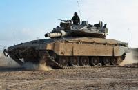
The first electromagnetic compatibility standards to be issued focused on naval vessels, where numerous detection systems (radar) and communication technologies (RF transmitters) need to coexist with dozens of electronic systems.
The need to maintain tight control over intense radio frequencies aboard warships loaded with fuel and munitions led the American navy to develop the first ever EMC standards (MIL STD).
Military EMC standards are now issued by France (GAM EG 13), the UK (DEF-STAN) and NATO (STANAG).
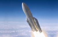
They also extend to other sensitive sectors such as: civil aviation (RTCA-DO standards), automobiles, space etc.
Equipment subject to qualification is generally concerned by mechanical, climatic and physico-chemical environments.
The implementation of EMC requirements related to automotive, military aeronautical or space qualifications requires exceptional means. It is as well about being able to carry out measurements in radiated emission up to 40 GHz, to test in immunity to RF fields at levels reaching 8000 V/m in pulsed, to implement indirect lightning tests according to the most recent specifications,... It is also necessary to be able to accommodate equipment with large dimensions as is the case with our system cages, to be able to meet the requirements in terms of servitude,...
Responsable des laboratoires CEM et Radio • Aéromil
Instrumentation implemented
- Electric field strengths of 10 kHz to 18 GHz
- up to 400 V/m in CW
- up to 600 V/m (Radar pulses)
- Magnetic fields DC - 200 kHz
- Bulk Current injection (B.C.I.)10 kHz - B GHz
- Stripline 50 Ω and 90 Ω
- AM, FM, pulse and combined modulations
DC measurements at 18 GHz:
- Current clamps 10 Hz - 1 GHz
- Magnetic field antennas (20 Hz - 30 Mhz)
- Electric field antenna (10 kHz - 18 GHz)
- Temporal analysis (DC - 500 Mhz)
- Electrical behaviour tests type ISO 7637 and ISO 16750
- Pulse ISO7637 (1, 1bis, 2a, 2b, 3a, 3b, 5a and 5b…) :
- Coupling clamp ISO 7637-3
- Pulse 4 and 4bis, pulse from restart, arbitrary waveforms, …
- Micro breaks.
- Climatic chamber -40°C to +110°C.
- Sub-transient voltage and specific waveforms, direct injection or coupling
- Power cuts (200 A)
- Low-frequency immunity for power supply (100 A)
- Testing for continuous networks
- Up to 30 kV (C = 150 pF, 330 pF, 500 pF, ... and R = 330 Ω, 2 kΩ, 500 Ω, 5 kΩ, ...)
- Radiated emissions as per CISPR 12 (measurements from 3 or 10m) and CISPR 25 from 150 kHz to 2.4 GHz (antenna method)
- Radiated immunity : ISO 11451-2 up to 200 V/m, from 10 kHz to 18 GHz
- Additional features to optimise our services:
- Test bench with 4 rollers for light or utility vehicle (2 or 4-wheel drive, ABS and ESP cycles, max. 100 km/h, etc.)
- Robot for operating vehicle pedals
- ...
MIL STD 462 was combined with MIL-STD-461D in MIL-STD-461E in 1999.
Instrumentation implemented
- Electric field strengths of 10 kHz à 40 GHz
- up to 3000 V/m in CW
- up to 10000 V/m Radar pulses (between 1 and 18 GHz)
- MSC Reverberation chambers with test methods DO160 and MIL STD461
- Magnetic fields 10 Hz to 150 kHz
- Bulk Current injection (B.C.I.) up to 1 Ampere from 10 kHz to 3 GHz
- AM, FM, pulse and combined modulations
DC measurements at 40 GHz:
- Current clamps 10 Hz - 1 GHz
- Magnetic field antennas (20 Hz - 30 Mhz)
- Electric field antenna (10 kHz - 40 GHz)
- Temporal analysis (DC - 500 Mhz)
- Transient overvoltage as perRTCA DO160 F/G, ABD 0100.1.8, ABD 0100 1.8.1C (A350), AMD 24C
- Sub-transient voltage and specific waveforms, by direct injection or coupling
- Power cuts
- Combined electrical (AC/DC) and climatic (-70°C - 180°C) testing
- Low-frequency immunity for power supply
- Testing to be performed on direct-current and alternating-current systems from 50 Hz to 800 Hz (3 x 45 kVA bays, can be paralleled to attain 135 kVA, 90 kVA, according to AIRBUS, BOEING, and DO 160 E/F/G section 16 specifications)
- Harmonic measurements
- Conducted susceptibilities MIL STD 461/AECTP 500
- on antenna ports ES 103, 104,105 and NCS 03,04,05
- in damped sine waves S 116, NCS 09
- Amplifiers, transformers, field systems and generators according to RTCA DO 160 C/D/E/F/G, AC 20-136, ABD 0100.1.2
- Generation of Multiple Stroke & Multiple Burst waves according to the following waveforms:
- WF1 or 4: 6,4/70 μs
- WF5B: 50 / 500 μs
- WF5A: 40 / 120 μs
- WF2: 0,1 / 6,4 μs
- WF3: 1 MHz et 10 MHz
- WF6: 0,244 / 4 μs
- Up to level 5 of DO 160 and even beyond for WF5A (Airbus ABD levels)
- Up to30 kV (C = 150 pF, 330 pF, 500 pF, ... and R = 330 Ω, 2 kΩ, 500 Ω, 5 kΩ, ...)
- Measurement of transfer impedance of cables and connectors in a triaxial cell (EN 62153-4-7, EN 62153-4-3) from 10 kHz to 200 MHz
- Measurement of transfer impedance of connectors by an injection line (EN 62153-4-7, EN 60512-23-3) from 10 kHz to 100 MHz
- Measurement of transfer impedance by a bulk current injection (BCI) clamp from 10 kHz to 200 MHz
- Measurement of shielding performance in a mode-stirred reverberation chamber (EN 61726) from 200 MHz
The RTCA DO-160G "Environmental Conditions and Test Procedures for Airborne Equipment" document sets out to define a series of test environments and procedures for on-board equipment in aircraft. The environments and procedures applied to an equipment item depend on the category defined in these documents, according to the type of aircraft, its conditions of use and how the equipment is installed in the aircraft.
This document is also referenced under the name EUROCAE ED-14G.
Electrical and electromagnetic environments - ECM testing
La MIL STD 462 was combined with MIL-STD-461D in MIL-STD-461E en 1999.
Instrumentation implemented
- Electric field strengths of 10 kHz à 40 GHz
- up to 3000 V/m in CW
- up to 10000 V/m Radar pulses (between 1 and 18 GHz)
- MSC Reverberation chambers with test methods DO160 and MIL STD461
- Magnetic fields 10 Hz to 150 kHz
- Bulk Current injection (B.C.I.) up to 1 Ampere from 10 kHz to 3 GHz
- AM, FM, pulse and combined modulations
DC measurements at 40 GHz:
- Current clamps 10 Hz - 1 GHz
- Magnetic field antennas (20 Hz - 30 Mhz)
- Electric field antenna (10 kHz - 40 GHz)
- Temporal analysis (DC - 500 Mhz)
- Transient overvoltage as perRTCA DO160 F/G, ABD 0100.1.8, ABD 0100 1.8.1C (A350), AMD 24C
- Sub-transient voltage and specific waveforms, by direct injection or coupling
- Power cuts
- Combined electrical (AC/DC) and climatic (-70°C - 180°C) testing
- Low-frequency immunity for power supply
- Testing to be performed on direct-current and alternating-current systems from 50 Hz to 800 Hz (3 x 45 kVA bays, can be paralleled to attain 135 kVA, 90 kVA, according to AIRBUS, BOEING, and DO 160 E/F/G section 16 specifications)
- Harmonic measurements
- Conducted susceptibilities MIL STD 461/AECTP 500
- on antenna ports ES 103, 104,105 and NCS 03,04,05
- in damped sine waves S 116, NCS 09
- Amplifiers, transformers, field systems and generators according to RTCA DO 160 C/D/E/F/G, AC 20-136, ABD 0100.1.2
- Generation of Multiple Stroke & Multiple Burst waves according to the following waveforms:
- WF1 or 4: 6,4/70 μs
- WF5B: 50 / 500 μs
- WF5A: 40 / 120 μs
- WF2: 0,1 / 6,4 μs
- WF3: 1 MHz et 10 MHz
- WF6: 0,244 / 4 μs
- Up to level 5 of DO 160 and even beyond for WF5A (Airbus ABD levels)
- Up to30 kV (C = 150 pF, 330 pF, 500 pF, ... and R = 330 Ω, 2 kΩ, 500 Ω, 5 kΩ, ...)
- Measurement of transfer impedance of cables and connectors in a triaxial cell (EN 62153-4-7, EN 62153-4-3) from 10 kHz to 200 MHz
- Measurement of transfer impedance of connectors by an injection line (EN 62153-4-7, EN 60512-23-3) from 10 kHz to 100 MHz
- Measurement of transfer impedance by a bulk current injection (BCI) clamp from 10 kHz to 200 MHz
- Measurement of shielding performance in a mode-stirred reverberation chamber (EN 61726) from 200 MHz


Emitech Group - Legal information